Introduction
It is assumed that the 3D modelling package used is Autodesk® 3ds Max® and the package used for authoring textures is Adobe® Photoshop.
The modelling package Autodesk® 3ds Max® was used to create Train Simulator, so this product appears in the examples provided. You can, of course, use other packages such as Blender™ or amabilis 3D Crafter. The package used here for authoring textures is Adobe® Photoshop. Again, you may use one of the many other packages available.
Regardless of the packages you use, the documents below should be used as a general guide to the processes to follow to build assets for Train Simulator.
| Important Note: For your chosen package, you may need additional plug-ins to export the assets into Train Simulator. Please check the availability of a suitable plug-in before you begin creating assets. |
General Guidelines
Orientation & Origin
All shapes should initially be created in the top viewport in 3ds Max, with the object facing up the screen.
Unless otherwise specified, a shape’s origin or pivot needs to be placed at the centre of the object's footprint (at coords 0, 0, 0). An easy way of doing this is to use a feature in 3ds Max to centre the pivot on the shape, and then move the pivot point vertically down onto the ground plane (the centre of the footprint).
Scale
All shapes should be built in metres to the correct scale. There should never be a non-uniform scale applied to a shape at any time.
If possible, it’s good practice to reset transform on the asset in 3ds Max just prior to exporting the shape.
Materials
It is important to use as few materials as possible and to use sensible, logical naming conventions on all materials regardless of whether they are required by the game engine or not. Some materials will need to be specifically named in an agreed naming convention so that the game engine can, for example, modify or replace the material. However, most materials will not be used specifically by the game engine and it will be up to the artist to name these. In these cases, these materials must still be given logical names so that the assets or scenes are easily understood by other artists viewing them for the first time.
Basic Construction
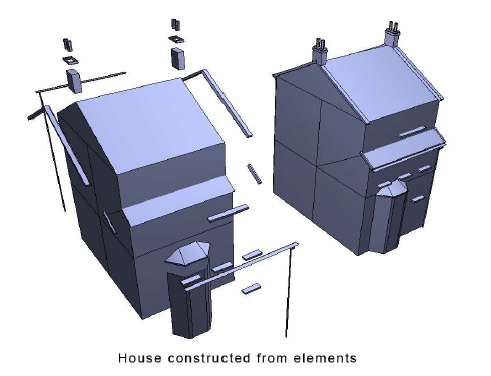
As a rule, small detail on the assets should NOT be stitched into the main shape. Put simply, the asset should be constructed by placing elements onto the main shape (see image below). This has a number of advantages:
- This will tend to keep the polygon count down.
- This will make the LODs easier to author later on.
As a general rule, textures for an object should exist below the object in a folder called "textures". Objects can share textures across objects within the same class. For example, a building can share textures with another building and a road vehicle can share textures with another road vehicle.
It is important that we try to keep a consistent texel size between neighbouring textures. If an inconsistent texel size is adopted, there may be a very low-resolution texture adjacent to a higher resolution texture and due to the filtering methods employed, one texture will be crisp and one texture will be very blurred. This is an undesirable visual effect.
Try to keep the number of different textures used on a shape down to a minimum. It is preferable to place all the textures for a single shape onto a single texture page.
Texture Groups
As the game supports a dynamic time of day and seasons, different texture groups for certain assets in the environment will be provided. Up to 4 texture groups for an asset are supported:
- Spring - Trees can have a different foliage
- Summer – Normal lighting conditions in summer (default)
- Autumn – Trees can have a different foliage
- Winter – Snow present in the texture
The textures will be identified through a suffix naming convention. The normal (default) textures for an object will have the texture names with no suffix.
The other textures required for the other seasonal variants will have the following suffix:
- _sp - for spring season
- _au - for autumn season
- _wi - for winter season
For example, consider a texture called "house_city_1". This texture only has one additional winter variant, called "house_city_1_wi".
Transparency & Alpha
If transparency is required on a texture:
- A NON-alpha shader (e.g TexDiff, TrainLightMapWithDiffuse.fx) must be used
- The image must be saved as a full 32-bit image (not palletised)
- The TRANS flag must be set on the material. For best results, only use full black and full white in the alpha channel (not the usual 256 colour grey scale); full black for transparent areas and full white for opaque.
There is NO true alpha sorting in the game engine. Therefore it is NOT advisable to use shaders with alpha. If shaders with alpha are used, the polygons using alpha may sort incorrectly in the game engine.
| Note: 256 colour images with an alpha channel are NOT supported in Train Simulator and will not display correctly. |
DX Texture Compression
DX Compression occurs on all textures by default. In most cases, this saves texture space and the visible drop in quality is unnoticeable. However, certain types of texture (perhaps textures with very subtle gradients) can appear 'jaggy' and 'banded' once compressed.
| Note: If the file has _nm as a suffix, the texture will not be compressed, BUT an uncompressed texture will take up more resources. |
Pre-Lighting the Scenery Objects
Larger assets will be pre-lit with ‘faked’ global illumination lighting on them as a second pass in the material. The lighting will not have any strong predominant direction because these objects will also be lit in-game by the dynamic lighting. The pre-lighting will allow the buildings to have diffused shadows under overhangs and around details. This will allow a richer appearance and will help to accentuate the polygonal detail on the assets.
| Note: See the Lighting Baking section for a detailed description. |
Hierarchy
A shape with a complex node hierarchy would be more expensive to render than a shape with a simple node hierarchy. Hierarchies should therefore only be used where necessary and should be kept as simple as possible. Again, the names of the nodes should follow the agreed naming convention.
LODs
LODs can be created easily and quickly if the assets are constructed as outlined in this document. If the correct construction approach is taken, elements can simply be deleted through the LODs. This approach will retain the overall shape of the asset whilst allowing the smaller insignificant elements to disappear through the LODs.
Advantages of this technique:
- Much quicker and simpler method of creating the LODs
- There will be no lighting anomalies as the shape goes through the LODs
- There will be no visible changes to the overall shape
Bear in mind that LOD 2 could still be viewable close to the camera, so extra time must be spent ensuring they will stand up to close-range viewing.
Animation
For animated assets, LODs need to be linked to their respective top-LOD. Since they will inherit the top-LOD’s animation, you need to remove any animation keys from LOD 2 and onwards.
Naming
All objects should follow strict naming conventions. Each name starts with a single digit representing the LOD level, followed by a 4-digit visible distance between underscores. After this, a logically chosen object name follows and the whole name is limited to a maximum of 31 characters.
All names should be lowercase characters throughout
where
- n = LOD level with 1 for the top LOD
- dddd = four-digit visible distance (Pad with preceding zeroes if necessary)
- name = logically chosen object name
If you enter 0000 in the distance field dddd it will make that LOD always render once active.
Example: LOD names for an asset called building01 could be:
1_0050_building01
2_0100_building01
3_1000_building01
The first LOD (the highest detail LOD) for Building01 will be visible from 0m to 50m, the second LOD being visible from 50m to 100m and the final LOD visible from 100m to 1000m. This shape will not be visible beyond 1000m.
Example: LOD names for an asset called tunnel04 could be:
1_0100_tunnel04
2_0500_tunnel04
3_0000_tunnel04
The first LOD (the highest detail LOD) for tunnel04 will be visible from 0m to 100m, the second LOD being visible from 100m to 500m and the final LOD will be visible from 500m onwards. This shape will not disappear beyond 500m and will always render.
General Considerations
This section will cover general approaches and considerations that will help artists understand how to get the best results from their artwork. It will explain why certain things need to be considered and help artists to understand why they sometimes do not get the desired results when viewing their artwork in the game.
Scintillation
The main problem occurs when there is fine vertical detail. This problem is most apparent if you have a single-pixel high, horizontal white line on a black background. The problem occurs when you have a large bright area with a large dark area below it with a sudden transition. The solution is to avoid these sudden transitions.
Consider trying to display overhead power lines in a game. Due to their shape, these objects when viewed in the distance will produce the worst-case scenario of horizontal lines of a single pixel width on-screen. This will produce some of the worst scintillation seen in games.
There is an easy solution to this - use an alpha texture on the object, and fade the alpha through the MIPs of the texture. It will be possible to make the power lines go translucent (gradual change through the MIPs) just at the point they reduce down to a single pixel width, thus reducing the scintillation problem.
Moiré Effect
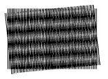
The moiré effect is a visual perception that occurs when viewing a set of lines or dots that is superimposed on another set of lines or dots, where the sets differ in relative size, angle, or spacing. In gaming terms, the moiré effect can be generated either deliberately or accidentally, in most cases accidentally.
The illustration below shows two sets of lines of equal thickness and equal spacing, but one set is angled at a few degrees while the other set runs vertically. The Moiré effect, in this case, appears as a set of thick, ill-defined near-horizontal bars.
In gaming terms, the moiré effect tends to be seen on noisy high contrast textures or textures with transparency in the distance. In this case, the effect is due to the lack of screen resolution relative to the resolution of the detail on the texture map.
The moiré effect on normal textures can be minimised by reducing the contrast of neighbouring pixels in the source texture.
Try to avoid very noisy textures by producing detailed but smooth textures.
The moiré effect can also be minimised through hand editing the textures MIPs, but this is time-consuming for any artist.
Tri-Stripping
A tri-strip can be defined as a group of ordered triangles all containing the same material properties. Tri-stripping is an efficient way of storing meshes due to the fact that it takes advantage of shared vertices.
The stripping ratio is calculated as the number of vertices divided by the number of triangles.
This ratio can be used as a measure of efficiency - if two shapes have been built using the same number of polygons but one has a lower stripping ratio, it can be deduced that the shape with the lower stripping ratio is more efficient.
Generally, the artist should try to keep the ratio for a textured shape less than 1.5. The closer the stripping ratio gets to 1.0, the more efficient the shape becomes - so, the lower this value, the better.
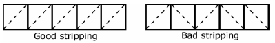
In its most basic form, a single tri-strip can only be created from polygons with their 'hidden' edges aligned in the same direction. From the figure below, the polygons on the left will form a single strip (very efficient) and the polygons on the right will form multiple strips (very inefficient).
Simply re-aligning polygon edges can sometimes increase the efficiency of a model by decreasing the overall stripping ratio value. Any of the following will create 'double' vertices, resulting in breaks to the tri-strips and therefore should be kept to a minimum.
- Smoothing group changes over neighbouring polygons.
- Different mapping projections over neighbouring polygons.
- Material changes over neighbouring polygons.
- Un-welded vertices on common edges.
Smoothing Groups
Assigning smoothing groups allows an artist to control which polygons should be grouped together and treated as a single continuous smooth surface, and which polygons should be isolated by hard edges and treated as separate facets (e.g. a cube). The process of assigning smoothing groups will affect how the vertex normals are stored for the object.
If a hard edge is required between two polygons, the artist must assign two different smoothing groups. This process will, in fact, double up the common edge vertices to create the 'hard edge' appearance. This 'doubling-up' occurs because the modelling package generates two new vertex normals for the hard edge.
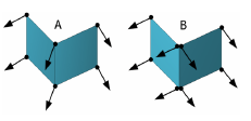
In the example below, object A has a single smoothing group and has 6 vertices with vertex normals. Object B required a hard edge and therefore two smoothing groups were assigned. This smoothing group assignment has now generated two new vertex normals at the ‘corner’ edge resulting in Object B now having 8 vertices.
Object A can be stored as 1 tri-strip but Object B can only be stored as two tri-strips. Therefore Object A is more efficient than Object B.
It is worth pointing out here that it's not just a case of keeping the total number of smoothing groups to a minimum. It's more important to keep the changes in smoothing groups between neighbouring polygons to a minimum. Basically, try to keep the hard edges in a shape to a minimum, therefore reducing inefficient doubled up vertices.
Mapping
Mapping coordinates are stored at the vertex level. Therefore, if two neighbouring polygons have separate mapping projections this process will again produce doubled up vertices at that shared edge, and will, therefore, break the tri-strip at that edge. Using this argument, it can be seen that individual face mapping will produce a high amount of doubled-up vertices and should, therefore, be avoided if possible.
Material Changes
Material changes will again break tri-stripping, due to the fact that each tri-strip by definition will only contain a single material.
Unwelded Vertices
Unwelded vertices on an edge will obviously break tri-stripping, as there are no shared vertices on that edge to begin with.