IntroductionThis section provides general information on how to create lofted geometry. Track is not covered in this section. Please see How To Create Track for detailed information on track construction. It is assumed that the 3D modelling package used is Autodesk® 3ds Max® and the package used for authoring textures is Adobe® Photoshop. The modelling package Autodesk® 3ds Max® was used to create Train Simulator, so this product appears in the examples provided. You can, of course, use other packages such as Blender™ or amabilis 3D Crafter. The package used here for authoring textures is Adobe® Photoshop. Again, you may use one of the many other packages available. Regardless of the packages you use, the documents below should be used as a general guide to the processes to follow to build assets for Train Simulator.
BasicsProcedural lofted geometry covers assets used for:
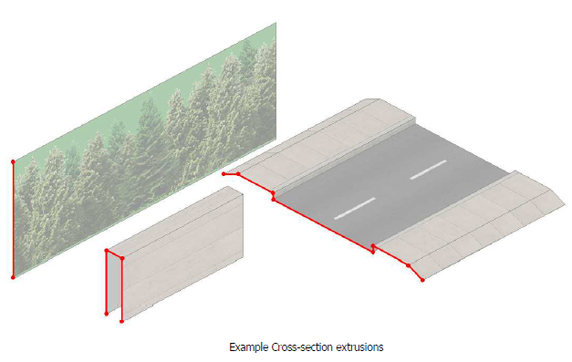
None of these assets can be previewed in the Blueprint Editor. These assets can only be placed (and hence visible) in the game at runtime. Cross-SectionsLoft cross-sections are created as extruded splines or edges in Max. These extrusions are exported as IGS files, and then converted as xsec files for use in-game. There are two important aspects of the extrusion to bear in mind.
 Loft ShadersLofts must be assigned with specific loft shaders. There are two loft shaders which can be used. One should be used on solid objects and another should be used on objects which require transparency (see-through areas).
MappingAs stated earlier, the cross-section in Max is only extruded to allow mapping information to be exported along with the cross-section data. The length of this extrusion is taken as the distance over which the textures will tile; i.e. if the single texture is mapped along the length of the extrusion, and the extrusion is 4m long, then the texture will be tiled once every 4m along the loft when viewed in-game. To summarise, adjusting the length of the extrusion will compress or stretch the texel size of the in-game loft texture. Generally, as a rule, try to keep the texels square.
On tracks, the rails and ballast do in fact tile in the logical direction (vertically). However, for lofts such as wire fences and distant building-lines, the texture needs to be created 90 degrees counter-clockwise to the normal in Photoshop. 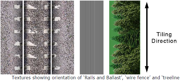 Population GeometryLofts can have modular pieces of geometry placed at regular intervals along the entire length of the loft. Up to 3 types of geometry can be specified per loft; start middle and end.
Examples of Uses
RoadsThese assets use road section blueprints. Road lofts are authored and lofted in a similar fashion to the track lofts but are less complex in structure. 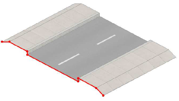 They would generally have a structure as follows:
FencesThese assets use simple loft section blueprints. An example fence: 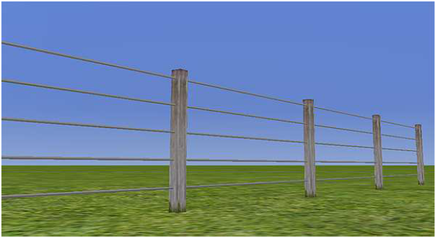 Here we are mapping a single wire fence texture along the loft, using the population geometry to place wooden posts along the loft. TextureRemember to author the texture 90degrees counter-clockwise, and that this loft would use transparency. The texture for wire fences looks as follows: Viaducts exist as bespoke or lofted structures. Bespoke StructuresThese are simply made to measure (usually straight) scenery structures built with a specific location in mind that usually span the gap in one whole section. Lofted StructuresThese offer a more general solution where viaducts need to follow a curved path. They can be built as a smaller modular piece (see diagram below) for both a specific location and as a more general structure, as they can be made to follow any path using the lofting technology. How they workA loft is created using the standard loft section blueprint. The loft itself references a simple cross-section that has a fully transparent texture applied using the LoftTexDiffTrans.FX shader. This will give the correct result of rendering the loft invisible as we don’t wish to see the loft itself. We are using this invisible loft to position a series of small modular pieces of a viaduct (see diagram below). 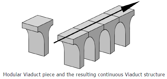 Population GeometryAs with other lofts, by specifying the modular viaduct piece asset in the middle geometry field in the loft section blueprint, this asset will be populated along the loft (which is invisible in this case) at a distance specified as the population frequency. Population frequency on viaductsIf the viaduct always follows a straight path then the population frequency can be equal to the exact length of the viaduct section. In this case, there would be no need for an overlap between each neighbouring section and they would be correctly positioned up against one another. However, if the viaduct follows a curved path (as in most cases) and the population frequency is set to the exact length of the viaduct section, then as the viaduct follows the curvature of the loft, small gaps will appear on the outer edge of the curve. See image below. 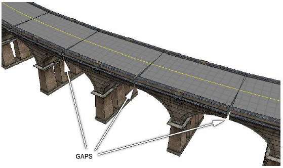 A simple solution to this problem is to specify the population frequency as a value which is slightly less than the length of the viaduct section. This will create a small area of overlapping geometry between each neighbouring viaduct section. This overlap area will mask the gap created as the viaduct follows the curvature of the path. See image below. 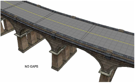 |
Reference Manual > Art Guidelines >