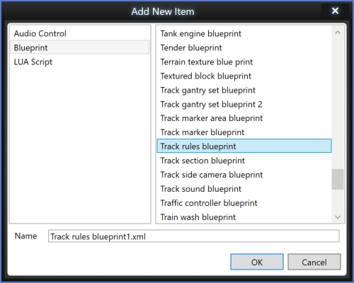
The track rules are created by selecting the Track Rules blueprint from the Blueprint choices.
Once created it is recommended that an appropriate name similar to that of the route is used to name the Track Rule.
Track Types
This section of the blueprint is used to list all the track types that will be listed in this Track Rule within the game. Those included in this list will not be the only types displayed, but they will be the ones placed at the top of available Linear Objects. All others not listed in this Track Rule will be separated by a dashed line.
To Add a Track Type to the blueprint first expand the track type field by clicking the + symbol and then click on the Insert First button.
Fill in the Provider and Product fields as appropriate, and place the location of your track type blueprint in the Blueprint ID field. For Train Simulator, we have located these at:
RailNetwork\Track\bath_temp_track01.xml
If you wish to add further track types, you can either click on the arrow button to the left of the previous track type added or use the Insert First button as before.
Default line type
The Line type defined here will apply to all track types entered into field 1. In the drop-down menu the options are:
- Mainline
- Yard
- Passenger
- Freight
Default speed limit
The default speed limits defined here will apply to all track types entered in field 1.
There are two fields:
Default line direction
The Line direction defined here will apply to all track types entered into field 1.
In the drop-down menu the options are:
Default electrification
The default electrification property defined here will apply to all track types entered in the first field.
In the drop-down menu the options are:
- None
- Overhead Wires
- Third Rail
- Fourth Rail
Gradient value
This defines a default gradient value to apply to all the track types in field 1.
Speed unit value
This determines what units of measurement are used for the speed values.
The choices in the drop-down menu are:
Track gauge
This determines the track gauge value. Changing this value will not alter the appearance of the track laid but will prevent track of a different gauge connecting with this gauged track.
Parallel distance
This defines the ground distance between the centre lines of two or more track lengths when two or more track lengths are placed at the same time.
Min Radius
This defines the minimum curvature with which a length of track can be placed. This can be defined per line type.
Catenary blueprint
With the Default Electrification field set to Overhead wires, when any track type is laid, the gantry blueprint ID defined here will be the gantry placed over the track.
Third rail blueprints
With the Default Electrification field set to Third Rail, when any track type is laid, the Third Rail blueprint ID defined here will be the third rail object placed over the track.
Fourth rail blueprint
With the Default Electrification field set to Fourth rail, when any track type is laid, the fourth rail blueprint ID defined here will be the fourth rail object placed over the track.
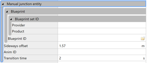
Manual Junction Entity
This field defines the blueprint ID for the manual junction indicator.
The fields are as follows: