Introduction
The World Editor allows you to create new routes or modify existing routes. This section introduces key World Editor tools and how to use them for simple route creation.
Getting Started
- From the main menu, click Build.
- Now you can either choose to edit an existing route by selecting one from the list or start a new route. For the purposes of this introduction, select a route from the list and click Edit in the lower-right corner.
You can also access the World Editor at any time you are in the game and driving/operating a train (during a Scenario) by using the key combination Ctrl + E, then clicking the world icon in the upper-left panel.
Once you have entered the World Editor, you can use the following keyboard commands to move the camera (your point of view) freely around the route:
- Up/Down/Left/Right Cursor Keys: Moves the camera forwards, backwards and sideways.
- Ctrl + Up and Down Cursor Keys: Moves the camera up and down in the y-axis.
- Hold the right mouse button and move the mouse: Pan the camera view.
- Scrolling the middle mouse button: Zooms the view in by adjusting the Field of View.
- Shift + Cursor Keys: Speeds up camera movements (also works with Ctrl + Up or Down cursor keys as Shift + Ctrl + Cursor Keys).
Saving
Press the F2 key at any time to save your route. You are also prompted to save:
- When you switch from the World Editor back to driving mode.
- When you open or close the Scenario toolbox.
- Exiting.
Press the Mode Switch button at the bottom right of the screen to return to the simulation.
Screen Layout
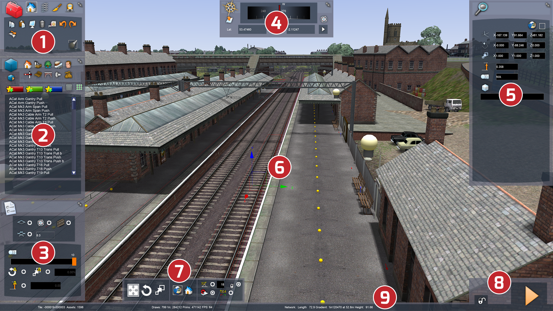
The World Editor has many information and menu panels (tabs), but to preserve screen space they are partially hidden. To display the menu, move the mouse over the edge of the screen where the menu resides as shown in the image below. To keep a tab permanently displayed, click on the pin icon at the upper right corner of each tab.
The numbers in the image above show you the position of the following tabs:
- Toolbox Tab
- Browser Tab
- Options Tab
- Navigation Tab
- Properties Tab
- Gizmo
- Gizmo Tab
- Mode Select/Lock Tab
- Status Bar
Each of these is described in detail in the sections that follow.
Toolbox Tab
Click on one of the icons at the top of the tab to display that toolbox's features. The four toolboxes are:
- Objects (house icon)
- Linear Objects (track icon)
- Painting (brush icon)
- Scenarios (train icon)
Which icon you have selected dictates the contents of the browser tab underneath it.
Browser Tab
The Browser tab contains the objects that can be placed into the world when Objects or Linear Objects are selected in the Toolbox Tab and has three areas. At the top area is a set of icons representing available objects by category.
The middle area contains a scrolled list of ‘assets’ or objects you can place in your world.
The bottom area shows the asset that is currently selected.
Options Tab
The panel on the bottom left of the screen contains the options for the toolbox currently selected on the toolbox tab.
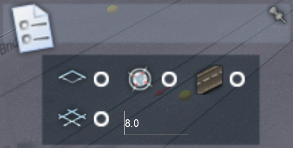
Also on this tab is radio buttons to toggle on/off the 1024m tile boundary lines; series and point markers (if any have been set up for the route) and a grid system.
The grid system is set to 8m spacing by default, but the value can be changed in the field next to the button. The centre of the grid is based on the current camera position and the lines of the grid draw North-South and East-West. Once an object is placed, if you have the grid displayed, dragging that object will snap it to one of the corner points of the grid.
Navigation Tab
The Navigation tab shows information on direction and orientation and consists of the following:
The compass shows the direction you are looking in. It also displays your current longitude and latitude. Edit the long/lat coordinates and select the white arrow on the bottom right of the panel to jump to those coordinates.
The 2D map button (the white sheet with an orange arrow on the left) toggles the 2D map on/off within the Editor; alternatively, you can press 9 to bring up the 2D map.
The route marker button (the grey-blue circle on the right) opens up a user-defined set of flags in the properties panel. Jump to one of these by selecting it and clicking the white arrow on the navigation panel.
Properties Tab
The Properties tab allows you to change the properties of certain objects. The properties tab opens automatically whenever you have performed an action that permits property editing.
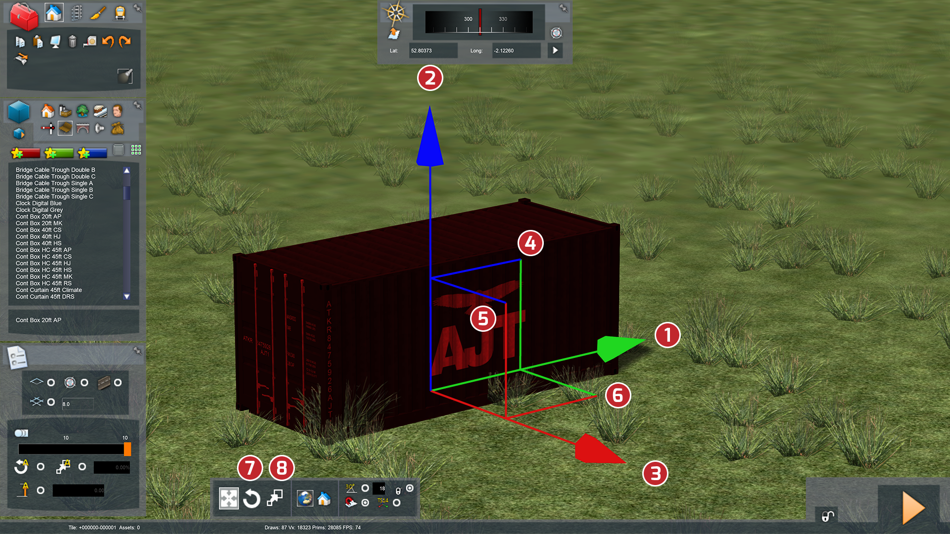
Gizmo
Whenever an object is selected in the 3D world, this gizmo will appear that allows you to move, rotate and scale the selected object (depending on the selected mode of the Gizmo Tab, see below).
Gizmo Tab
This tab allows you to set the mode for the Gizmo. By default, it is set to the movement mode which means that whenever you select an object, you can only move the object. The other modes are Rotation (circular arrow) and Scale (Boxes).
You can also change the coordinates mode here, from World (globe icon) to Local (house icon).
Rotation and terrain snapping can also be toggled here. Snapping effectively allows you to constrain the placement of objects to the terrain (makes it easier to place objects), and when rotating objects, to specific angles.
A legacy gizmo mode is also provided for those who prefer the Train Simulator 2014 (and previous) gizmo style.
Mode Select / Lock
The area at the bottom right of the screen provides two functions.
The lock icon allows you to lock certain functionality to prevent you accidentally changing items in a route that will prevent the functioning of pre-existing Scenarios. To unlock the route, click the lock. To re-engage it, click the lock again.
The Mode Switch icon takes you back to driving mode. If you are editing a route in Free Play mode and have not selected a train then the camera will remain detached when you return to driving mode, allowing you to fly around the route and view it with the correct lighting and effects. If you entered the World Editor from a Scenario or had already selected a train in Free Roam Driving, you will be returned to the locomotive when switching to drive mode.
Status Bar
The information displayed on the status bar depends on the toolbox currently selected on the toolbox panel.
ToolTips
Some objects in the world display information in the form of a tooltip, which hovers when the mouse is held over the object. Track information is displayed in the form of a tooltip.
Display Filtering
On a complete route, there may be a lot of information displayed when you enter Editor Mode. This can be confusing and make selecting some objects difficult.
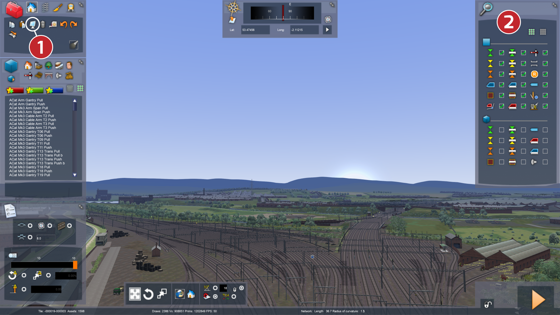
Using the Display Filter
On the Toolbox tab is the Display button (1), which lets you filter the infrastructure which is being displayed in the editor. Clicking this button opens the Properties Tab (2) which in this case has a selection of checkboxes. Moving your mouse over an icon next to a checkbox brings up a tooltip showing the name of the icon.
By default, all the options are checked. This means every piece of infrastructure is displayed and can be selected.
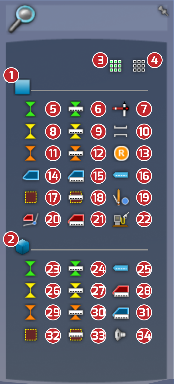
The image below shows how the display properties tab is laid out:
- Affects 2D map display area
- Affects World Editor display area
- Check all boxes
- Uncheck all boxes
- Platform Markers
- Platform Names
- Signals
- Siding Markers
- Siding Names
- Tunnels
- Destination Markers
- Destination Names
- Reversing Points
- Non-Player Train
- Non-Player Train Names
- Destination Boards
- Area Markers
- Area Names
- Manual Junctions
- Immediate Paths
- Service Names
- Fuel Points
- Platform Markers (World Editor)
- Platform Names (World Editor)
- Destination Boards (World Editor)
- Siding Markers (World Editor)
- Siding Names (World Editor)
- Player Train Names (World Editor)
- Destination Markers (World Editor)
- Destination Names (World Editor)
- Non-Player Train Names (World Editor)
- Area Markers (World Editor)
- Area Names (World Editor)
- Ambient Sounds (World Editor)
You can see that the properties panel is divided in half. The bottom-half affects the World Editor, the top-half, the 2D map. Uncheck any of the boxes in the bottom half of the tab to hide the corresponding infrastructure item and make it unselectable.
Alternatively, click the icon on the top right to clear all the boxes at once. In the images below you can see the effect of having all items checked and then unchecked. Once something is hidden you are able to select items behind it; particularly useful for the large sound markers.
Using the Display Filter in the 2D Map
With the 2D map open (by pressing the icon or 9) you can see there is a Display icon (the monitor) at the bottom right. Clicking this icon on the 2D map will also bring up the properties tab. This time, only the top-half of the icons are displayed as these relate to the infrastructure displayed on the 2D map.
Again, uncheck any of the boxes in the bottom-half of the tab to hide the corresponding infrastructure item.
Alternatively, click the icon on the top-right to clear all the boxes at once.
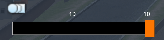
The Detail Level Slider
Another way to hide objects and preview the objects displayed on different detail level settings is to use the detail level slider which is located on the Options tab.
Grab the orange slider and move it to change the currently displayed detail level. The current detail level number is displayed above the middle of the bar. Moving the slider to 10 will display more detail and moving the slider left will hide objects.
Whether an object is hidden or not is determined by the detail setting of the individual object.
The Detail Level Slider allows you to control the level of graphical detail displayed for each object. A player can determine the number of objects that are drawn on their simulation. Lowering this number can improve performance on lower specification computers.
- Double-left-click an object in the world to show its properties.
- Use the orange Detail Level Slider to change the current detail to a value between 1 and 10.
The detail level is worked from the highest level of detail backwards. A value of 10 means that the object will be displayed on all 10 settings of the slider. A value of 1 is the lowest, meaning it will only display the shape for 1 detail level (or only at the highest detail level). For example, setting a detail level of 3 on a building will mean it draws on the top 3 highest settings on the slider and not be displayed for the other 7.
Setting object detail levels will aid performance on lower spec machines as it hides objects at lower settings. The slider on the Options tab directly correlates to the sliders in the main game settings. Main Menu > Settings > Graphics > Advanced > Detail Sliders.
Manipulating Objects
The Object Tools in the Toolbox tab allow you to place objects in the 3D world. You can also rotate, scale and delete the object.
Object Placement
To place an object, select a Toolbox (Objects, Linear Objects, and Scenario) from the top of the Toolbox tab and then select from the resulting specific object list. Move over the 3D world and the object appears on the cursor ready for placement. Left click to place the object. Left click and drag to rotate the object before it’s placed. Once placed, another object of the same type becomes available on the cursor for repetitive placement. Right-click to exit object placement.
Object Selection
To manipulate an object in the 3D world, hold the mouse cursor over the object to highlight it, and left click on it to select it.
Object Movement
A transform gizmo appears over a selected object, enabling detailed movement of the object:
- Left click and hold on the green arrow to move the object along the z-axis (1).
- The blue arrow moves it in the y-axis (2).
- The red arrow moves the object along the x-axis (3).
- You can also move along two axes simultaneously by selecting the intersecting blue and green points (4) to move the object along the z- and y-axes.
- The red and blue intersecting points (5), moves along the y- and x-axes.
- The red and green intersecting points (6), moves along the x- and z-axes.
- You can change to rotation mode by selecting icon 7 from the Gizmo Tab.
- You can change to scaling mode by selecting icon 8 from the Gizmo Tab.
Additional movement controls are from the keyboard. These tend to move the object more slowly offering finer control than using the transform gizmo:
- V and B keys move the object up and down.
- G and F keys rotate the object clockwise and anticlockwise.
- N and C keys move the object toward the camera and away from the camera
- J key snaps the object to the height of the terrain
Selecting Multiple Objects
Holding the left mouse button and dragging the cursor over the terrain makes a circular lasso appear and widen. Release the left mouse button to select all objects within the lasso.
To select multiple objects with more precision, hold the Ctrl key and left-click on the individual objects.
Whichever method you use to select multiple objects, a single transform gizmo is displayed that controls all of the selected objects.
General Object Properties
Double left-click on an object to open the Properties tab for that object.
Specific Object Types
Some objects in the Objects toolbox have unique methods of placement, selection and movement:
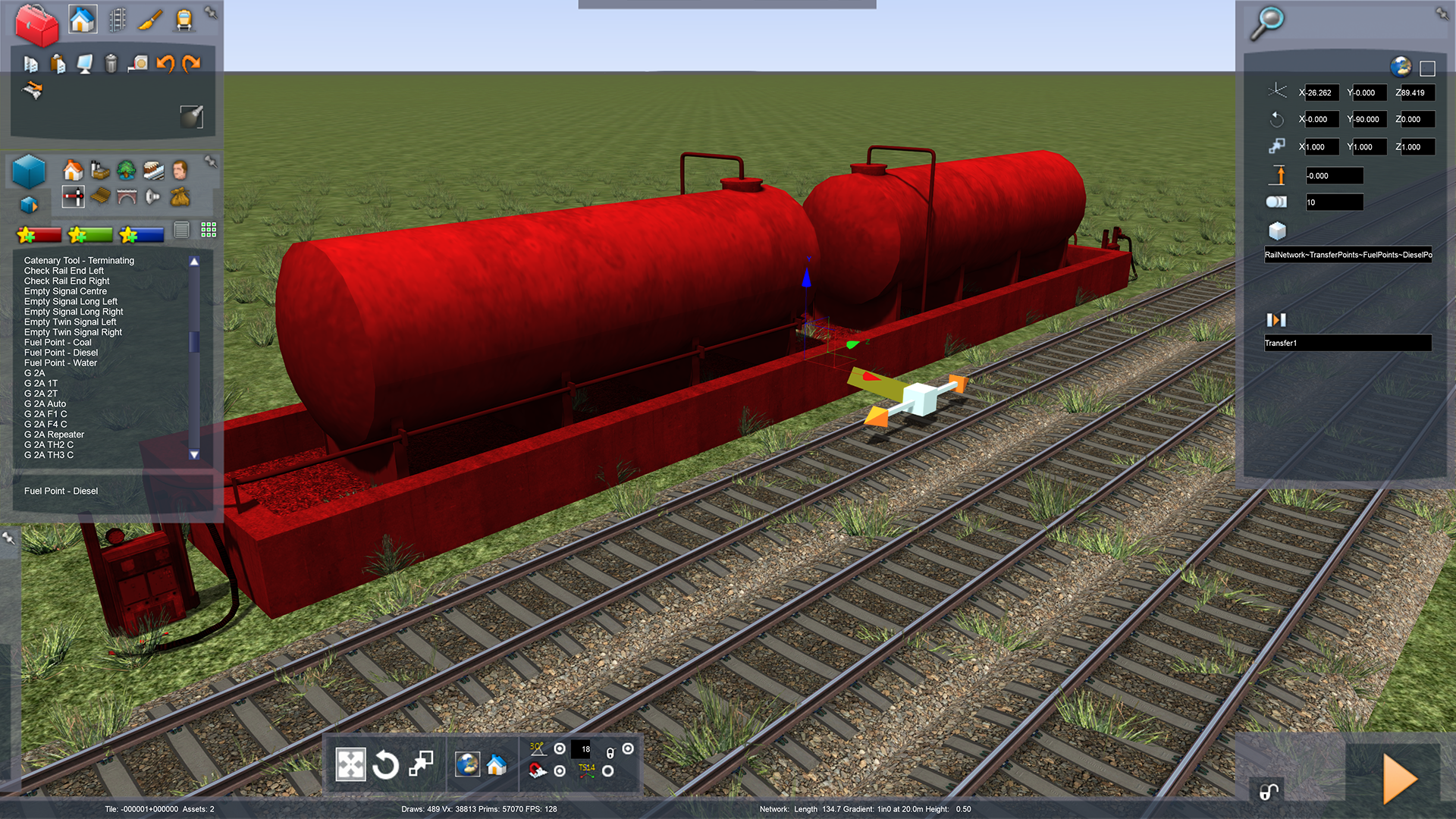
Track-Linked Objects
Track-linked objects are objects/assets that have a specific connection with a point or area of a track, but which are not actually part of the track, such as a fuelling point. To place a track-linked object:
- Select the Objects toolbox to display a list of specific Objects
- Select a track-linked object from this list.
- Left-click to place the object near the track, then move the mouse cursor towards the track.
- A track link appears on the track. Left-click to place the link.
For objects which can span multiple tracks, such as mileposts, left-click and hold, then drag across parallel tracks. A link appears on each track you move the mouse cursor over.
Some signals have multiple links, which need to be placed at various places on the track network. Left click as many times as required on the relevant tracks to place all the track links.
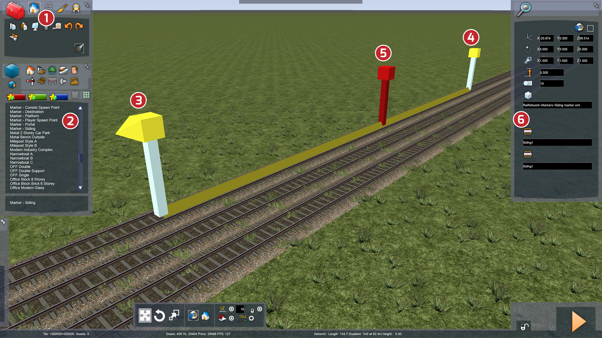
Track Markers
Track markers are placed along the track for navigation in Scenarios.
- Select the Object toolbox.
- Select a linear marker from the available Objects.
- Left-click to place the start point.
- Move the mouse and left-click to mark the endpoint.
- Double-clicking the marker's central post will bring up the Marker's properties (6).
- You can set the name of the marker in the Marker's properties.
- If you wish to alter the marker's position or length, you can do so by moving the end-posts (3) and (4).
Water Tile/Decal Placement
Select a water or decal tile (such as a tunnel hole decal) from the Browser tab and left click to place it. When water or decals are selected, transform gizmos become visible along the edges.
Ambient Sounds
Localised and ambient sounds are placed in the same way as normal objects. In the World Editor, you can hear each sound as you move the camera close to it. There is also a sphere indicating the audible range of the sound.
Linear Object Toolbox
The linear objects tools allow you to place linear objects such as tracks, fences and roads.
Linear Object Placement
- Select the Linear Objects toolbox.
- Select a linear object from the Browser Tab
- Choose the position in your route where you wish the Linear Object to be placed. An indicator appears on the terrain to show the start location and direction of the linear object.
- Hold down Left-click and drag the mouse to change the start direction of the linear object.
- Release Left-click to start placement
As you move the mouse over the terrain, an outline shows where your linear object will be placed. Left click again to place the linear object following the outline. When the outline is yellow, you are following a straight line.
Another indicator of the same type appears at the end of the previously placed linear object for continuation. Right-click once to cancel continuous linear object placement, right click twice to cancel linear object placement completely.
Linear Object Selection
You can only select linear objects when the Object or Linear Object Toolbox is open. Select linear objects in the same way as other objects.
Linear Object Movement
When you select a linear object, a transform gizmo appears as it does with other objects minus the yellow ball for orientation as linear objects cannot be tilted in this way. Some linear objects (mainly linear water objects) can be widened using the extra transform gizmo that appears.
Linear Object Properties
Double left-click on a linear object to open the properties panel, if applicable for that object.
Linear Object Tools
Select Tool
Changes the properties of specific areas of linear objects (where available). Select the tool, click on the linear object once to start the selection then drag the mouse along the linear object. Once the required length is selected, click again to finish and view the properties for that section.
Split Tool
Splits linear objects into sections. Select the tool and place the cursor above a linear object to see a marker showing where the split will occur. Click to complete the split. To split linear objects of multiple widths, such as four parallel tracks, place the cursor above the outer linear object. Hold the left mouse button and drag the mouse cursor perpendicular to the linear object so it spans the other linear objects. A series of indications appear of where the splits will occur. Click again to complete the splits.
Join Tool
Joins sections of linear objects of the same type together. Select the tool, click on one of the linear objects you want to join, then click on the other object.
Offset Tool
Runs a linear object parallel to another linear object. After selecting a section of a linear object using the select tool, select the offset tool and then select a type of linear object from the browser list. Click on the end indicator of the yellow offset lines on the side you want the offset to occur.
Weld Tool
Welds valid junctions on track linear objects. When you select the Weld tool, a grey box indicator appears above all junctions that can be welded. Click an indicator box to weld that junction automatically.
Important Note: You must weld any separate sections of track to form a continuous line. A train will derail if it runs over unwelded tracks. |
CrossOver Tool
Creates crossover junctions on track linear objects. Select the tool then select a track linear object from the Browser tab and move over to a section of multiple tracks. An indicator appears representing the start of the crossover junction. Click on a track and move the mouse over to a parallel track. An indicator appears, showing where the crossover will be placed. Left click again to complete the crossover. Click on the indicator above the crossover to create a symmetrical double crossover.
Gradient Tool
Edits the gradient of a linear object. Select the tool and move the mouse cursor over a linear object. A gradient point appears under the cursor, along with any existing gradient points on the linear object. Click on the left mouse button to place a new gradient point; click on an existing gradient point to select it ready for editing. Drag the mouse to alter the gradient point’s vertical setting. Drag over to parallel linear objects to create multiple perpendicular gradient points. To delete a gradient point, click on it and press the DELETE key. To snap a gradient point to the terrain, select it and press the L key.
Blend Tool
Blends the textures between two different types of track that are joined together. Select the tool, click on the two tracks objects and they are blended together automatically.
Smooth Gradient Tool
Smooths the transitions of gradients in a selected area. First, using the Select Tool, mark a section of track that you wish to smooth. Once selected, click the Smooth Gradient Tool and the transitions will be smooth.
Track Property Views
To view a track’s properties, press the spacebar to toggle between the following track properties:
- Fully rendered track (as it will appear in a play session).
- Line type
- Line direction
- Line speed
- Track sounds
- Track Electrification
- Track-linked objects view
Gradient Editing
It is often necessary to change the gradient of linear objects after they have been laid. There are a number of ways of achieving this. However, this section details the recommended method.
When you click on the gradient icon in the Linear Object toolbox, all current gradient points are displayed and new gradient points can be inserted. To raise or lower an existing gradient point, select that point, and hold down the left mouse button while dragging the mouse up and down.
Moving the gradient point in this way will then alter the gradient of the track all the way from the selected gradient point to the next one in each direction, overwriting any previous gradient information.
This can produce undesired results if you have previously laid track using set gradients. To have finer control and minimise any risk of overwriting gradients in areas outside of the direct area you wish to edit, you should then insert additional gradient markers.
Placing a gradient marker each side of the point you are editing to define the area which is being altered offers greater control.